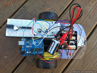
Adriano, the Arduino Robot | Step 1 (Basic Operation)
 |
| Arduino Robot | Step 1 (Basic Operation) |
Component List
- Arduino Uno. I plan to switch to the smaller Arduino Nano to see whether the Uno is overkill for this project. Subsequently, I also plan to see how far I can get with the ATtiny85V, PICaxe 08M2 and any other smaller micro-controllers worth trying.
- Breadboard. I know how to solder (and you should, too), but it's not much fun at all and risks burning out components. Breadboards are great for prototyping, making modifications on the fly, and building projects incrementally, in phases (not unlike Agile software development). Later on, you can solder the robot into a permanent gadget, if you really want to (and have no need to reuse the components). This is why I want to experiment with smaller/cheaper micro controllers units (MCUs), although the cheap prices for the MCUs are often offset by the complicated/expensive setup required to program them.
- 9V Battery. To power the Arduino. It's a good idea to keep the Arduino circuit separate from the circuit driving the motors for several reasons. One, the two circuits might require different voltages to drive them. Two, doing so protects the Arduino from the noise produced by induction motors. Three, the Arduino might not directly be able to provide the current required to drive the motors (I tried and failed to run the motors directly off the Arduino digital pin output).
- Custom Arduino Software/Program. The actual program that causes the robot to move in the pattern you see in the video.
- Jumper Cables. Invaluable for connecting components using a breadboard. For example, jumper cables are used to carry the digital output signals from the Arduino to the breadboard.
- Test Leads with Alligator Clips. These are also invaluable when you don't have the ideal connectors handy. I used these to connect the 9V battery to the Arduino, using jumper cables.
- 2WD Chassis. This is the base for the robot.
- DC Motors. These are attached to the chassis.
- Wheels. Attached to the motors.
- Caster Wheel. Attached to the back of the chassis. This provides a simpler option than a 4WD robot, which is harder to make and manage, in part because you then have four motors to manage instead of just two.
- 6V Battery Case. This is what powers the circuit for the motors.
- 2N2222 Transistors. These happen to be the most popular semiconductor of all time. I used the TO-92 packaging components to bridge the Arduino circuit to the motor circuit. The digital output from the Arduino is wired to the transistor base (via a 560 ohm resistor in series). When the base receives a signal from the Arduino, it allows current to flow form the collector to the emitter, thereby completing the circuit for the motor and causing the motor to run.
- 560 Ohm Resistors. As described above.
- Double-Sided Tape and Velcro. Invaluable for attaching things (e.g. the breadboard, the Arduino and the 9V battery) to the robot chassis so that they don't fall off while the robot is operating and they can be easily removed when you need to use them for other prototypes.
Next Steps
This step is just the beginning on what I expect to be a long road with the following enhancements and/or modifications.
This step is just the beginning on what I expect to be a long road with the following enhancements and/or modifications.
- Add a distance sensor (SR04) for obstacle/precipice avoidance.
- Add light sensors (LDRs) for light following behavior.
- Add infrared (IR) remote control capabilities. At least for me, the VS1838 module (a little board with a built-in LED) was a miserable failure. So, I switched to the raw TSOP4838 (not a module), and it works like a charm (with the Keyes remote control that shipped along with the VS1838 module).
- Add an H-bridge using the L293D chip (I pulled it off my Arduino Motor Shield, which I found to be overkill) to allow the Arduino to reverse motor direction without rewiring.
- Experiment with smaller micro-controllers, e.g. the Arduino Nano, the ATTINY85V, and the PICAXE.
- Experiment with alternate wireless remote control technologies, including Wi-Fi and Bluetooth wireless.
- Store robot configuration (e.g. MRU motor speeds) in EEPROM using I2C serial communication from the Arduino.
- Add LEDs to indicate status, e.g. remote control signal received (blink), light following behavior on/off, turning indicators/blinkers.
- Use Wi-Fi/wireless communication (e.g. using the NRF24L01+ board) to send remote signals to a server, a form of client to server logging. This approach might help to troubleshoot why the robot seems to occasionally ignore remote key presses even though they are received by the Arduino (as demonstrated by the LED flash response). Is it because the Arduino is too busy to process the instruction or because the remote signal code got mangled during transmission? The log, collected via wireless communication, will tell us.
References
- Make: Electronics by Charles Platt. A delightful book with detailed pictures, drawings and explanations. Easily the best modern book on the subject.
- Arduino Cookbook (Second Edition) by Michael Margolis. Encyclopedic treatment of all that you can do with an Arduino micro-controller.
- Arduino in Action by Martin Evans. There a lot of Arduino books in the market. But I found this one to be one of the most useful books.
- YouTube Videos. Especially the ones by Jaidyn Edwards and Jeremy Blum.
Click here to view the subsequent steps in this series.
Step 2 (Remote Controlled)
Step 3 (L293D Controlled)
Step 2 (Remote Controlled)
Step 3 (L293D Controlled)


Comments
Post a Comment